
These two different adapters PCB are intended to convert the RFM69 Module’s castellated solder pads (which are a 2mm spacing) to fit a more standard 0.1″ 2.54mm PCB spacing of prototype boards etc.
Both PCBs were originally intended for use with the RFM69HW module, but can be used for other models of the same dimensions and pin spacing.
Smaller version
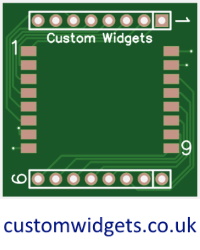 The smaller module is more “breadboard friendly”, having a header spacing of 9 x 2.54mm, so it will fit on common breadboards with a set of breadboard holes on either wide. The design does this by rotating the RMF connections by 90° to the header connections. You may solder the antenna directly to the RFM Module, or header connector.
This PCB is approximately 28mm x 28mm.
Larger version
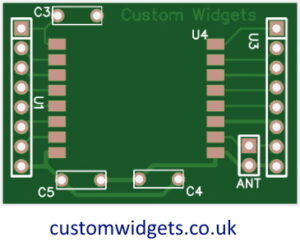 The larger PCB is more flexible (having more antenna options, and component placement positions) – and it will fit wider (or two side-by-side) breadboards – having a header spacing of 13 x 2.54mm. The RFM connections are in-line with the header connections making it a wider PCB.
Reference Design
This PCB also has through-hole pads to accommodate the two decoupling capacitors as specified in the HOPERF reference design for the RFM69HW, and through-hole pads to solder the reset capacitor (which is optional in the HOPERF reference design).
There are also multiple options for you to attach an Antenna. You may solder the antenna directly to the RFM Module, or to the “ANT” pads, or the header connector.
The 2.54mm connector pins are a 1:1 match to their corresponding castellated solder pads.
This PCB is approximately 38mm x 26mm.
Where to buy
These buying links will pass you to external websites
Bezels and Displays